Representative End User Clients


Representative Automation Clients
Representative Software Clients


The public’s perception of additive manufacturing has been highly polarized over the past decade. In recent years, however, the hype has waned, the pessimism eased, and the industrial outlook shifted towards more thoughtful consideration of how and where the technology can and should be applied. ARC Advisory Group recognizes the power of additive manufacturing to enable wholly new product designs and business strategies. But some significant hurdles remain to be addressed.
Additive manufacturing is still in its infancy for industrial manufacturing applications. As a result, the ecosystem that supports it (hardware and software suppliers, automation suppliers, standards associations, etc.) is also immature.
From the very early steps of product design, to the final steps of post processing, stakeholders across this ecosystem must address a number of significant hurdles before the technology can be widely embraced for demanding industrial applications. These include the need for “outside the box” thinking when designing new and innovative products for additive manufacturing production and the need to adopt new tools and methods to validate materials, in-process control, and final part inspection.
A modern approach to design engineering is based on examining constraints: the requirements, rules, and relations that define the context of a design. Some constraints are fundamental, such as those imposed by the laws of physics and chemistry. Others can be more flexible, such as those imposed by convention or economics. An engineer can define his or her project based on the design space bounded by these constraints. Every point within this space represents a design that satisfies all constraints; but not all satisfactory designs are equally attractive. The challenge is to identify the best design among all viable solutions. To do this, engineers will often impose new or stricter constraints to reduce the design space and thus narrow down the field of candidates. In this way, adding constraints is as much a part of design as searching for solutions.
But what happens when constraints are removed? In some cases, removing a narrow or burdensome constraint makes an engineer’s job easier. In others, what’s left is a larger design space, making it more challenging to identify the best solution within that space.
With the introduction of additive manufacturing as a production process, design engineers must now contend with a design space no longer bounded by conventional manufacturing constraints. Complex geometric structures and surface contours that were once not economically feasible or possible to manufacture can now be achieved. With additive manufacturing, complexity of geometry is not a constraint. As a result, new tools and methods must be applied to accelerate the search for winning candidates within this broadened design space. By incorporating such tools into their product development programs, end users can begin to realize the full potential of additive manufacturing. Innovative companies will move from producing parts designed for conventional manufacturing, to producing parts that can only be manufactured through additive technology, and finally, to producing products that require additive manufacturing design tools for their very ideation.
Generative design is an automated, iterative process that takes constraints as an input and produces designs that meet those constraints as an output. A design engineer can augment 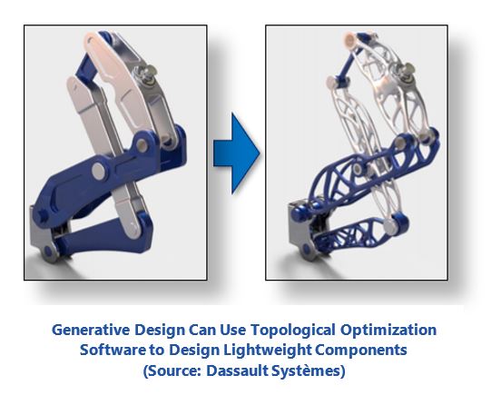 the output indirectly by either reducing the number of candidates, modifying their characteristics, or adjusting the minimum and maximum values of the constraint variables. In this manner, engineers can use generative design as a tool to reduce - by orders of magnitude - the time spent searching for viable designs within a given design space.
The most recognizable application of generative design for additive manufacturing is designing lightweight components using topological optimization software. The workflow is relatively simple: within a CAD environment an engineer will pre-select material properties, apply loading and boundary conditions, geometric requirements, such as mating surface sizes and locations, set constraints, such as maximum stress or deflection, and finally set a target mass for the final part. A topological optimization algorithm will take these inputs and produce a three-dimensional model that meets all the criteria.
Unless additional geometric constraints are applied, the resulting parts often have a spindly structure with complex surface contours. The geometries that result are often too complex for conventional manufacturing, but perfectly suited for additive manufacturing. The linkage shown here is an example of topological optimization performed by Dassault Systèmes generative discover software.
Additive manufacturing’s unique capabilities also enable creation of parts that incorporate complex multi-scale design. For example, lattice structures, which are often far too complex for conventional manufacturing, can be easily incorporated into additive designs. Lattices are two- or three-dimensional architectures comprised of a network of nodes and beams that can reduce part weight dramatically while retaining structural integrity. In addition to providing excellent strength-to-weight ratios, lattice structures can be incorporated into designs to absorb shock, dampen vibrations, or act as a heat exchanger. The image shows the combination of both generative design and lattice structure design, created by Frustum software, which was acquired by PTC this year.
On an even smaller scale, the micro-structures of surfaces can be con-trolled in certain additive manufacturing processes. In the biomedical field, for example, the intentionally rough surface of implants is designed to promote osseointegration, the structural and functional connection between living bone and the load-bearing implant.
Additive systems can also produce single parts made of multiple materials. Now, in addition to both geometric and multi-scale design freedom, engineers must also consider how they can optimize their products through multi-material design. Some material jetting systems, for example, can create single parts with diverse material properties by selectively depositing different types of photopolymers during the build process. These parts can vary in stiffness, strength, color, translucency, heat resistance, and a myriad of other characteristics. Even the gradient at which a material characteristic changes throughout the part geometry can be controlled precisely through automated blending of the base materials during production. The opportunity this technology presents greatly exceeds standard injection molding, where material properties are dictated by the bulk material of the part, which is usually determined by the requirements of some critical feature.
Part consolidation is the process of combining what would typically be multiple parts of an assembly into a single printed component. Functional consolidation is when additive manufacturing is used to add new functionality to a part. Functional consolidation can result from part consolidation.
Through part consolidation, manufacturers can drastically reduce the number of process steps required to manufacture a product. This reduces labor requirements and can even obsolete entire manufacturing lines. The resulting simplification of product supply chains is a key driver for decentralizing production via additive manufacturing. Part consolidation can also help eliminate potential quality issues and failure mechanisms associated with the eliminated process steps and components: leaky O-rings, bad welds, stripped bolts, and so on.
Functional consolidation can be achieved through part consolidation but also by implementing some of the previously mentioned design techniques. For example, flexibility can be introduced to certain areas within a multi-material design to create compliant mechanisms. Cooling channels are another example of how additive manufacturing can be used to integrate new functionality into a part, such as with the Siemens gas burner shown.
The two gas burners shown here were highlighted at last year’s Hanover Fair and provide a perfect example of part and functional consolidation. The display in-between the two burners, a row of monitors, told the story of the digital thread connecting the new design to its final construction. At the left end of the display was the conventional burner made of 13 components, 18 welds, and a thermal barrier coating, the sum of which required a 26-week lead-time. At the right end of the display sat the redesigned part made with EOS powder bed fusion technology; a single integrated part with no need for thermal barrier coating and a reduced, three-week manufacturing lead-time.
Individually, the unique capabilities afforded by additive manufacturing can be used to create significant step changes to products. Combined, they can inspire entirely new, innovative designs. The challenge is to find or create the necessary tools and product development methods to foster such innovation. As it stands, most design engineers today have neither the training nor the tools to take full advantage of additive manufacturing. Universities have recently begun to offer additive manufacturing courses and additive manufacturing system providers also offer training courses, but the scarcity of capable and experienced engineers in this field is evident.
Additive manufacturing, while providing tremendous benefit to design freedom, does impose some significant challenges and constraints. There are seven primary classifications for additive manufacturing systems, each with its own unique set of challenges. The seven classifications are:
Even within one of these segments, such as power bed fusion, the choice of vendor or even the specific system model may present a different set of constraints. A simple, yet common constraint is the available build volume. The more complex constraints have less to do with the space in which the part is being produced and more with how the process of manufacturing the part will affect the end result. These types of challenges require much more thought and consideration to overcome.
To address such challenges, product lifecycle management (PLM) providers have been developing tools that can simulate the entire build process of the more common additive manufacturing technologies. For example, within the last two years, nearly all the major PLM providers have rolled out simulation products for powder bed fusion. The software is conceptually like computer aided manufacturing (CAM) software for computer numerically control (CNC)-based manufacturing. However, instead of creating a tool path that simulates the removal of material, it simulates a laser path and the resulting sintering or melting of powder material. This simulation can provide valuable insight into any warping behavior that may occur due to residual stress in the finished part. As shown, the more advanced solutions can then recommend or even make changes to the digital model of the part to compensate proactively for the expected warpage.
Continued development of accurate process simulation is imperative for the growth of industrial additive manufacturing. Currently, the design of complex additive parts often requires an iterative process of design, manufacture, redesign. Moving this process into the digital world will decrease development costs and time of such projects by several orders of magnitude.
A critical part of DfAM is the design of support structures. For most AM processes, scaffolding must be built-up along with the part. This is primarily to support overhanging structures during the build process, anchor the part to the baseplate or build a platform and, in some cases, function as a heat sink to reduce warping. Determining the location, size, and geometry of these structures is an engineering task in and of itself. Failure to design an appropriate support system can lead to severe quality issues and unusable parts. Many of the process simulation tools offered by PLM providers now also offer solutions that automate the support structure design process. These solutions will also suggest optimal part orientation during the build as well as part arrangement for multi-part builds. These tools can greatly increase the throughput of additive manufacturing systems.
As a relatively new set of manufacturing technologies, additive manufacturing is slowly finding its way into serial production. ARC Advisory Group sees three main hurdles that the additive manufacturing ecosystem must overcome to move beyond its current niche in prototyping to become an established production process.
The first hurdle relates to quality, specifically, the quality control of the raw materials (powders, filaments etc.), the AM machines themselves, the printing process, and final part inspection.
The second is the lack of automation. Automation for loading, unloading, and integrating AM machines into serial production is still immature compared with traditional manufacturing processes. Only through faster cycle times and some degree of automation can AM compete with traditional production techniques. As we’ll discuss in a future ARC Strategy Report, standards and certifications will be required to over-come these hurdles.
Last, but not least, the post processing of the additive manufactured parts remains a critical and surprisingly difficult hurdle for volume production.
Quality is a facet of all steps in the production process, from incoming material inspection, through process and part monitoring during manufacturing, to final inspection. The shift towards mass customization calls for new quality control paradigms for AM. Here, the effects of various AM complexities on quality inspection, monitoring, and process optimization must be considered. However, there is a lack of comprehensive knowledge and corresponding standards as to how to assess quality along the AM process. This is a prerequisite for a broader application for industrial use. With a sound, comprehensive quality strategy, industrial users of additive manufacturing technology can:
Even before starting the actual additive manufacturing process, selecting the right materials can go a long way toward assuring the quality of the part or product produced.
ARC Advisory Group clients can view the complete report at ARC Client Portal
If you would like to buy this report or obtain information about how to become a client, please Contact Us